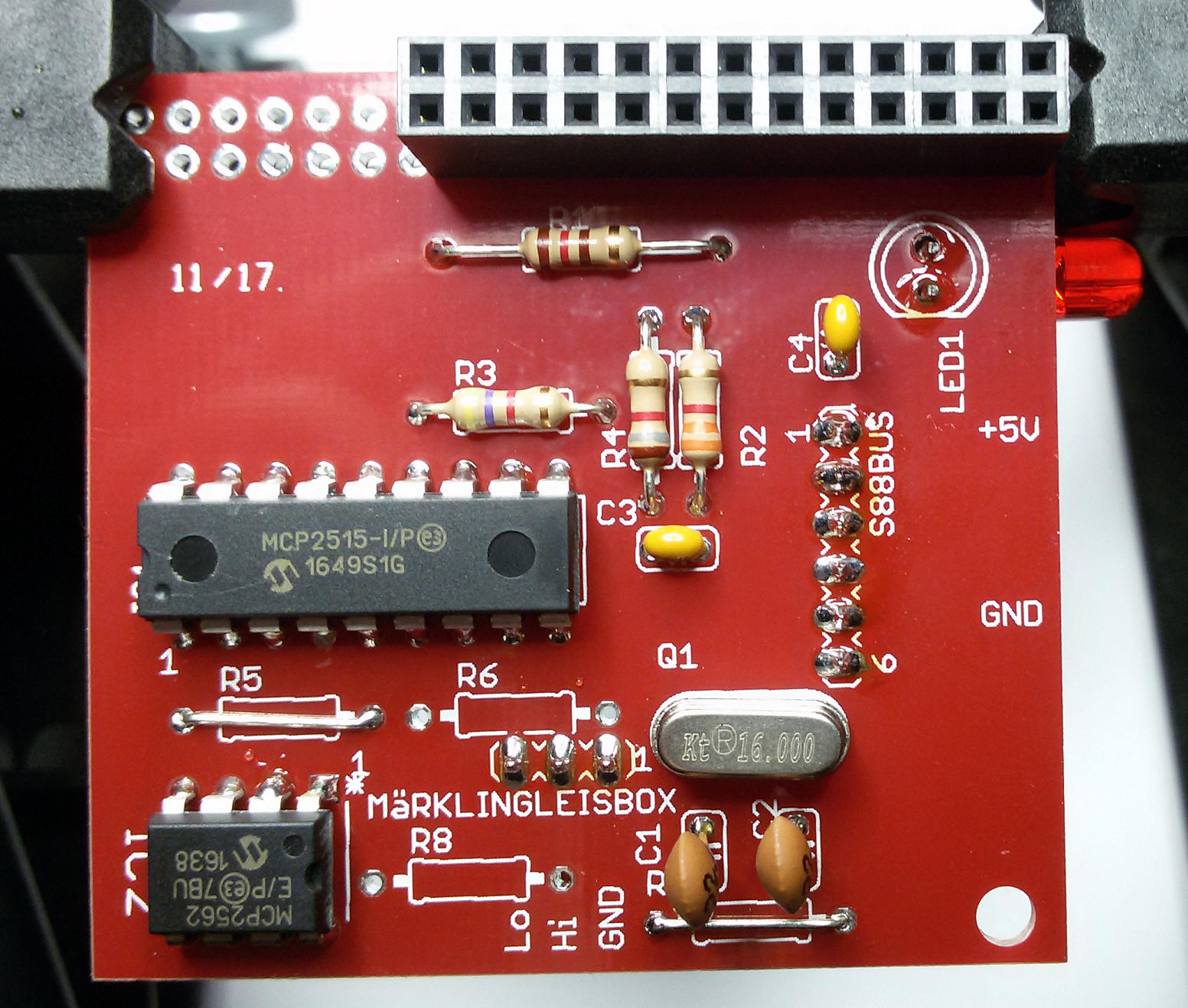
General Board soldering hints:
Start with the lowest parts like resistors first, and start to solder the parts from the middle of the board to the outside.
My personal line is the following:
R4 - R2 - R3 - R5 - R6 - R8 - R7 - R1 - Q1 - IC1 - IC2 - C3 - C4 - C1 - C2
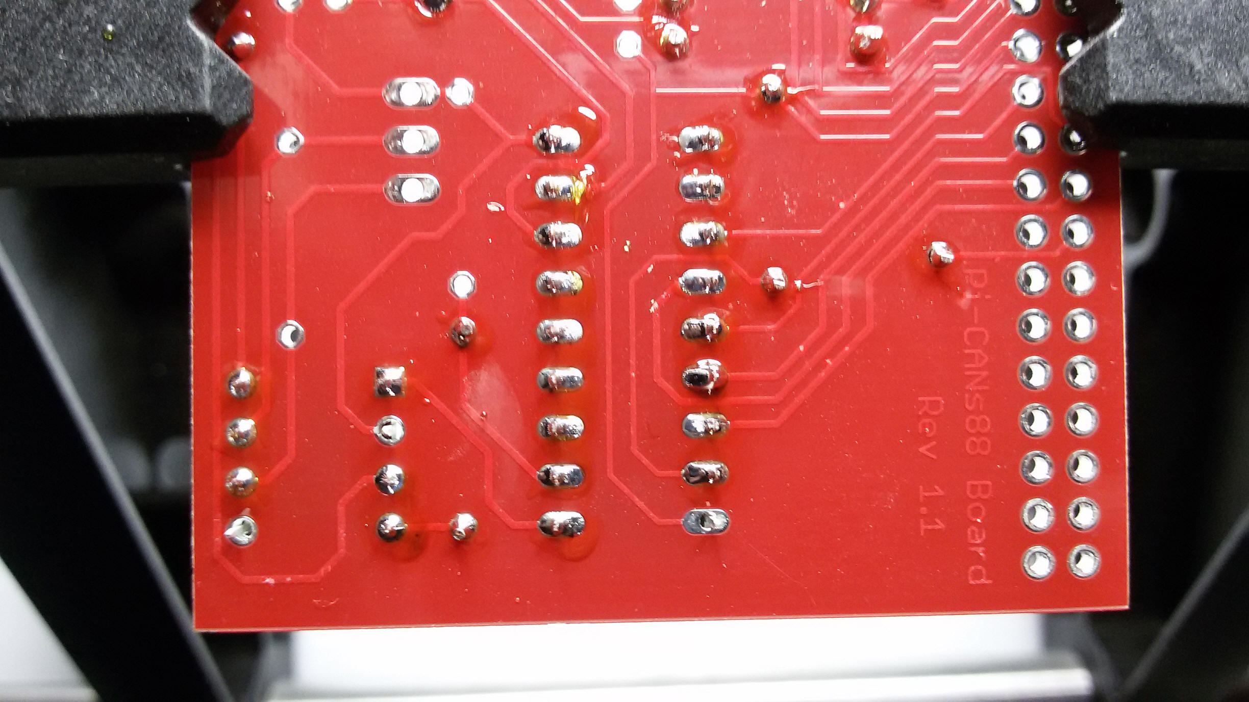
Turn around the board.
6 Pin Connector - 3 Pin Connector - LED Red
Turn around the board.
2x13 Pin Connector to PI
In case of Board Version 2, start to
solder R3.
Cut off the legs of R3 and use them as bridge for R5 and R7.
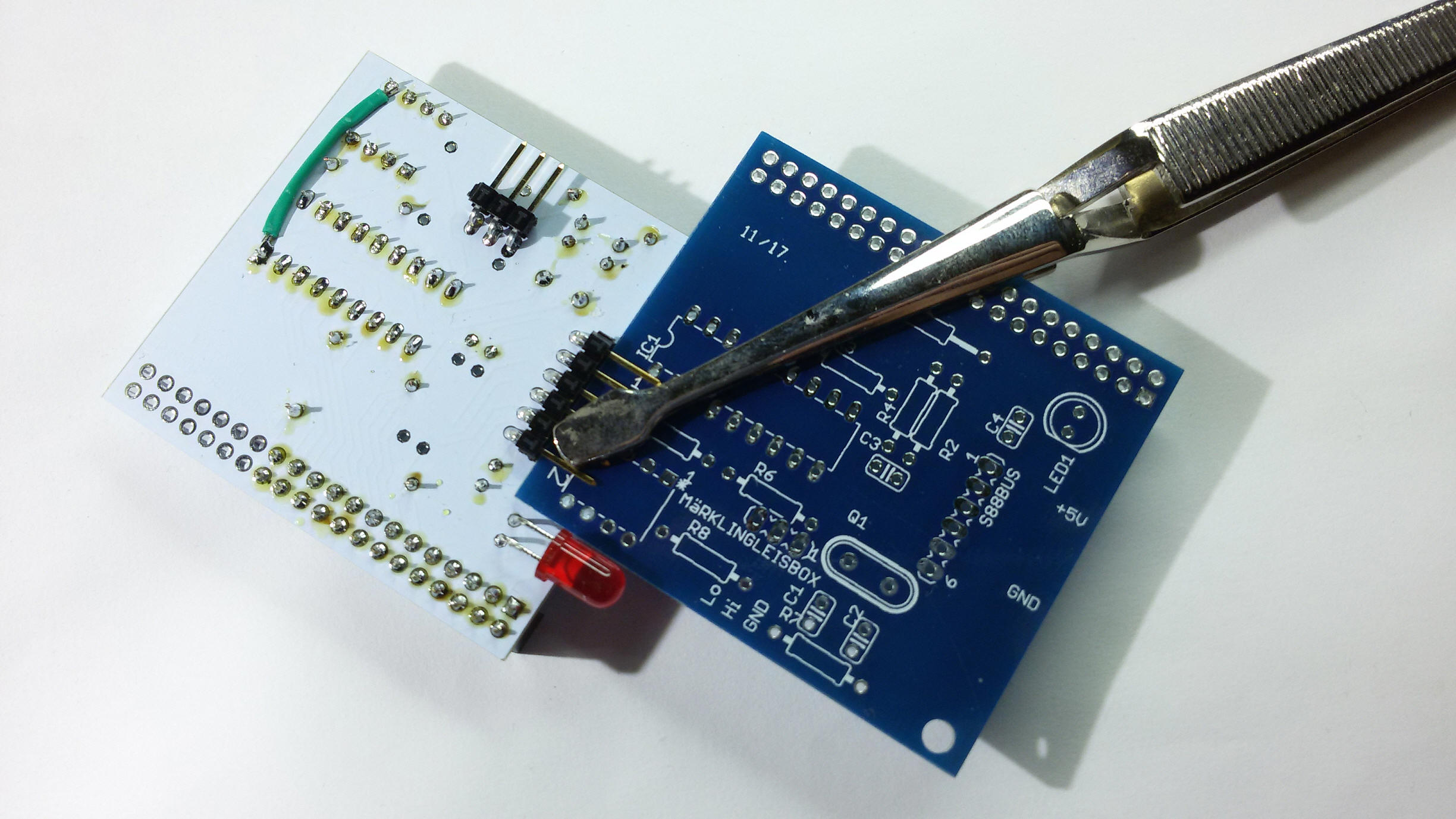
On soldering the 6 and 3 Pin Connectors, leave a little gap to
the board.
I use to use another board like in below picture to leave more space for the
future connector:
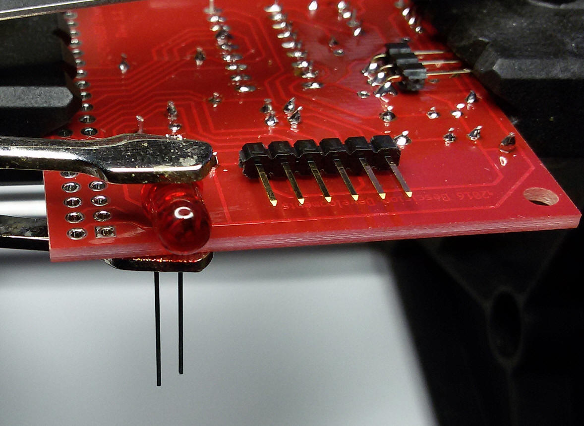
Pay attention on soldering the LED. The large leg of the LED is "+" and belongs to the outer side of the board:
Soldering V2 on a V1-Board:
Here is a little guide how to solder the new version 2 circuit diagram on a version 1 PCB.
Leave R6 away. Shorten R5 and R7 with a wire:
(You can use the legs of R3 as wire)
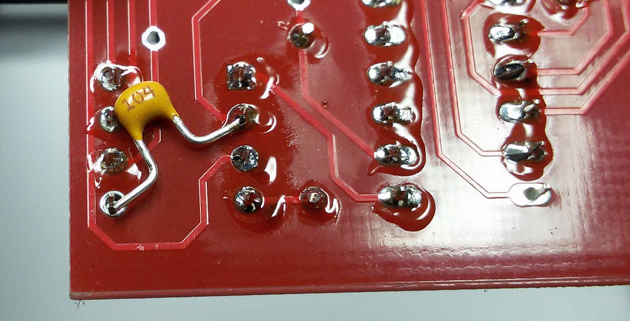
On soldering the ICs: Do not solder Pin 18 of MCP2515 and Pin 2 and 5 of the other MCP:
Position C5 and solder Pin 2:
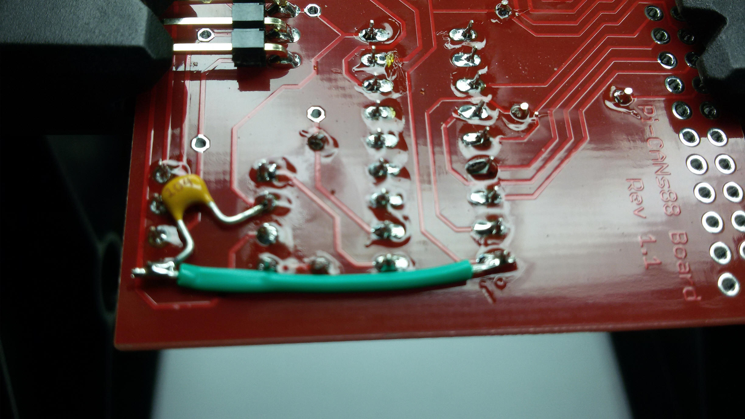
Position a wire and solder the unsoldered two pins:
Final soldered Board V2: